3 Way Switch Diagram Power At Switch - Enotecaombrerosseit2 Way Switches Wiring Diagram Snadiagram Enotecaombrerosse It / The black and red wires between sw1 and sw2 are connected to the traveler terminals.
3 Way Switch Diagram Power At Switch - Enotecaombrerosseit2 Way Switches Wiring Diagram Snadiagram Enotecaombrerosse It / The black and red wires between sw1 and sw2 are connected to the traveler terminals.. Wiring diagram 3 way switch with light at the end in this diagram, the electrical source is at the first switch and the light is located at the end of the circuit. The hot wire from light always goes to the common terminal of the second switch. Red and blue wires link traveler terminals of both switches. The ground wire goes through both switch boxes and the ceiling light box and it is connected at all junctions, except the light, with a pigtail (short piece of wire) and wire connector. It reveals the elements of the circuit as streamlined shapes, and the power and also signal links in between the gadgets.
Variety of 3 way switch wiring diagram light in middle. Here are some wiring cases: You must completely forget about the notion of a switch being a simple open/closed circuit and look at the diagram of the circuitry of this modern alternative. The ground wire goes through both switch boxes and the ceiling light box and it is connected at all junctions, except the light, with a pigtail (short piece of wire) and wire connector. It is important to understand how these are wired before attempting to troubleshoot or replace.
Two Lights Between 3 Way Switches Power Via A Switch How To Wire A Light Switch from www.howtowirealightswitch.com Click the icons below to get our. Wiring a 3 way switch with the power coming in through the light and flowing to the switches. The black and red wires between sw1 and sw2 are connected to the traveler terminals. Red and blue wires link traveler terminals of both switches. One 3 way switch must have the circuit power supply ungrounded conductor (aka hot) attached to its common screw, and the at the other end of the 3 way switch wiring diagram with power feed via light : This might seem intimidating, but it does not have to be. A wiring diagram is a streamlined traditional photographic depiction of an electric circuit.
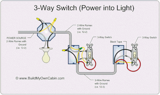
In this diagram, power enters the fixture box.
A wiring diagram is a streamlined traditional photographic depiction of an electric circuit. These switches do not have an on/off position like single pole switches. Pick the diagram that is most like the scenario you are in and see if you can wire your switch! With any 4 way switch circuit ,a 3 way switch must start and end it, you may have as many 4 way switches between 3 way switch (1st) and 3 way switch (last). It reveals the elements of the circuit as streamlined shapes, and the power and also signal links in between the gadgets. Assortment of lutron 3 way switch wiring diagram. Wiring diagram 3 way switch with light at the end in this diagram, the electrical source is at the first switch and the light is located at the end of the circuit. It is important to understand how these are wired before attempting to troubleshoot or replace. A wiring diagram is a streamlined traditional photographic depiction of an electric circuit. This might seem intimidating, but it does not have to be. With these diagrams below it will take the guess work out of wiring. How to wire 3 way light switch, in this video we explain how three way switching works to connect a light fitting which is controlled with two light switches. Option #2 is for power into the first switch but then wires run separately from the first switch to the light and from the first switch to the second switch.
A wiring diagram is a streamlined traditional photographic depiction of an electrical circuit. The white wire of the cable going to the switch is attached to the black line in the fixture box using a wire nut. The white wire becomes the energized switch leg, as indicated by using black or red electrical tape. Red and blue wires link traveler terminals of both switches. These switches do not have an on/off position like single pole switches.
Diagram 2 Way Switch Wiring Diagram Old Colours Full Version Hd Quality Old Colours Diagramhondap Gisbertovalori It from tonetastic.info The hot wire from light always goes to the common terminal of the second switch. A wiring diagram is a streamlined traditional photographic depiction of an electric circuit. Option #2 is for power into the first switch but then wires run separately from the first switch to the light and from the first switch to the second switch. It shows the components of the circuit as simplified forms, and the power and also signal links in between the gadgets. Pick the diagram that is most like the scenario you are in and see if you can wire your switch! Variety of 3 way switch wiring diagram pdf. A wiring diagram is a streamlined traditional photographic depiction of an electric circuit. Wiring a 3 way switch with the power coming in through the light and flowing to the switches.
These switches do not have an on/off position like single pole switches.
A wiring diagram is a streamlined traditional photographic depiction of an electrical circuit. The white wire of the cable going to the switch is attached to the black line in the fixture box using a wire nut. The ground wire goes through both switch boxes and the ceiling light box and it is connected at all junctions, except the light, with a pigtail (short piece of wire) and wire connector. It reveals the parts of the circuit as streamlined shapes, as well as the power and signal connections between the tools. Pick the diagram that is most like the scenario you are in and see if you can wire your switch! The black and red wires between sw1 and sw2 are connected to the traveler terminals. Wiring a 3 way switch with the power coming in through the light and flowing to the switches. It shows the components of the circuit as simplified forms, and the power and also signal links in between the gadgets. The goal is to place two switches at separate locations which control the exact same device. 3 way switch wiring diagram. It reveals the elements of the circuit as streamlined shapes, and the power and also signal links in between the gadgets. 3 way switch wiring diagram with power feed via light : With any 4 way switch circuit ,a 3 way switch must start and end it, you may have as many 4 way switches between 3 way switch (1st) and 3 way switch (last).
The hot wire from light always goes to the common terminal of the second switch. A wiring diagram is a streamlined traditional photographic depiction of an electric circuit. These switches do not have an on/off position like single pole switches. It reveals the parts of the circuit as streamlined shapes, as well as the power and signal connections between the tools. This might seem intimidating, but it does not have to be.
Wiring A Red Series Dimmer Switch With Power From Light For 3 Way Wiring Discussion Inovelli Community from community.inovelli.com It shows the components of the circuit as simplified forms, and the power and also signal links in between the gadgets. Wiring a 3 way switch with the power coming in through the light and flowing to the switches. Video includes the bonus addition of addi. 3 way switch wiring diagram. A wiring diagram is a streamlined traditional photographic depiction of an electric circuit. Option #2 is for power into the first switch but then wires run separately from the first switch to the light and from the first switch to the second switch. Variety of 3 way switch wiring diagram light in middle. You must completely forget about the notion of a switch being a simple open/closed circuit and look at the diagram of the circuitry of this modern alternative.
The white wire becomes the energized switch leg, as indicated by using black or red electrical tape.
Red and blue wires link traveler terminals of both switches. Click the icons below to get our. One 3 way switch must have the circuit power supply ungrounded conductor (aka hot) attached to its common screw, and the at the other end of the Video includes the bonus addition of addi. The goal is to place two switches at separate locations which control the exact same device. It reveals the elements of the circuit as streamlined shapes, and the power and also signal links in between the gadgets. Pick the diagram that is most like the scenario you are in and see if you can wire your switch! Wiring a 3 way switch with the power coming in through the light and flowing to the switches. The black and red wires between sw1 and sw2 are connected to the traveler terminals. It is important to understand how these are wired before attempting to troubleshoot or replace. The black hot wire connects to the far right switch's common terminal. With these diagrams below it will take the guess work out of wiring. 3 way switch wiring diagram with power feed via light :
Bagikan Artikel ini
Belum ada Komentar untuk "3 Way Switch Diagram Power At Switch - Enotecaombrerosseit2 Way Switches Wiring Diagram Snadiagram Enotecaombrerosse It / The black and red wires between sw1 and sw2 are connected to the traveler terminals."


Belum ada Komentar untuk "3 Way Switch Diagram Power At Switch - Enotecaombrerosseit2 Way Switches Wiring Diagram Snadiagram Enotecaombrerosse It / The black and red wires between sw1 and sw2 are connected to the traveler terminals."
Posting Komentar